Menu

هل تبحث عن كسارة أو صانع رمال أو مطحنة مشروعك؟

Block Diagram Of Cement Mill Pdf Customer Case. block diagram of cement mill pdf carecallsystemscouk. plc based automated clinker cooling system for cement raw mill is a ball mill meant for grinding limestone, . Get Price And Support Online; block diagram of a rotary kilns design. block diagram of cement mill pdf writeofpassage.
Process Flowchart Diagram or PFD is also known as the system flow diagram or SFD. The main reason for using process flowchart is to show the relation between major parts of the system. Process Flowchart Diagram or PFD does not include minor parts or components of the system like piping ratings or .

A pugmill or pug mill is a machine in which clay or other materials are mixed into a plastic state or a similar machine for the trituration of ore. Industrial applications are found in pottery, bricks, cement and some parts of the concrete and asphalt mixing processes. A pugmill may be a fast continuous mixer. A continuous pugmill can achieve a thoroughly mixed, homogeneous mixture in a few ...
Process flow diagrams (PFDs) are used in chemical and process engineering. These diagrams show the flow of chemicals and the equipment involved in the process. Generally, a Process Flow Diagram shows only the major equipment and doesn't show details. PFDs are used for visitor information and new employee training.
Figure 4a is a cutout diagram of a largecapacity (200 hp) pellet mill. Although power transmission by means of a Vbelt drive is shown (1), gear drive coupling of motor to the main shaft (2) is also possible. Feed from a surge bin (3) is metered into the steam conditioning chamber by a .

serving motors larger than 1/2 HP Plan for one circuit to serve no more than three 1/3 HP motors, two 1/2 HP motors, or one 1 HP motor or larger Use at least a 50amp, 240volt, 2wire with ground circuit and outlet for a welder Locate it just inside the door, OR Add a .
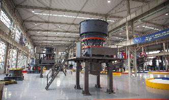
Portland Cement Manufacturing Process Description17 Portland cement is a fine powder, gray or white in color, that consists of a mixture of hydraulic cement materials comprising primarily calcium silicates, aluminates and aluminoferrites. More than 30 raw materials are known to be used in the manufacture of portland cement, and these
If your meter doesn't display those readings, you've got a bad switch or a broken power or ground wire. Download an electrical diagram and check the power and ground wires leading to the switch to isolate the problem. For proper window motor replacement, you'll need to replace the entire regulator assembly, not just the motor.
Various automation processes in the industry need control of AC induction motors using AC drives. Presented here is a robust system for switching on/off, varying the speed and direction of rotation of an industrial 3 Phase Induction Motor using VFD and PLC. We use here Delta AC motor drive for its ...
4 Phone • • Fax EXPEDITE YOUR ORDER MIXING TIME 4" 6" Slump General Use MIXING TIME 4" Slump or Less Paving Use Certified by the Manufacturer to comply with the concrete plant mixer test procedures for
83 Centrifugal force outward Fc mp 2 Dm 2 () is the angular velocity, mp is the mass of any particle (media or charge) in the mill and Dm is the diameter of the mill inside the liners. Gravitational force Fg mpg () The particle will remain against the wall if these two forces are in balance ie.
Foundation layout, Electrical diagram, Operation manual Brief Introduction Of DASION HZS35 Concrete Batching Plant DASION HZS35 concrete batching plant (35m3/h) consists of material batching, mixing and electric control system, which is professional equipment for ready mix concrete production, such as plasticity/dry concrete.
A 'read' is counted each time someone views a publication summary (such as the title, abstract, and list of authors), clicks on a figure, or views or downloads the fulltext.
LANL Standard Drawings and Details either (1) depict required format/content or (2) are templates that are completed by a Design Agency (LANL or external AE) for a design drawing package, in a manner similar to specifications.
Coalfired power plant diagram: The coal power plant diagram shows the components of the plant and the different stages of transforming the chemical energy (coal) into electrical energy as: We started with the boiler or the steam generation system; as we supply the coal from coal bunkers via coal conveyors to be crushed into coal mills.
